This article was originally published at Basler's website. It is reprinted here with the permission of Basler.
Robots capable of quick, precise and seemingly effortless grasping and placement of goods: until recently, this seemingly-simple task actually required a long and difficult period of setup and training. Robots with a sense of space, capable of interacting with co-workers almost as a human would, seemed more like sciencefiction than daily reality. Nevertheless, there are many changes afoot right now in 3D imaging processes, with 3D technology generally taking on a larger role in machine vision.
What are the major 3D methods?
Robots, factory and logistics automation and the medical sector are all fertile fields for 3D, as it can open up unprecedented opportunities for resolving complex image processing tasks. 3D image processing is most applicable when volumes, shapes and 3D positions and orientations of objects are required, such as in the logistics sector for transporting merchandise quickly and securely from A to B. But which technology stands behind the creation of 3D images?
There are currently four different processes for generating 3D image data:
- Time-of-Flight
- Laser triangulation
- Stereo Vision
- Structured light
How do they differ from one another?
Different procedures and fields of application
Stereo vision and structured light
Stereo vision works similarly to the human eyes. Two 2D cameras take images of an object from two different positions and calculate the 3D depth information using the principle of triangulation. This can be difficult when viewing homogeneous surfaces and in poor lighting conditions, as the data is often too muddled to produce solid results. This problem can be addressed with structured light to lend the images a clear, predefined structure.
One clear plus for stereo vision is its high accuracy in measuring objects with small working range. That high accuracy usually requires reference marks, a random pattern or that light patterns created by a structured light source be projected onto the object. Stereo vision is typically effective at the coordinate measurement technique and the 3D measurement of workspaces. However, it is frequently less suitable for production environments, because it involves high processor loads and increases overall system costs when used in industrial applications.
Laser triagulation
Laser triangulation uses a 2D camera and a laser light source. The laser projects a line onto the target zone, to be captured using a 2D camera. The lines bend as they touch the contours of the object, so the distance between the object and the laser light source is calculated based on the position coordinates of the lines in multiple photos.
Because structured light is incorporated in the method, there are rarely issues with tricky surfaces or low ambient light. Laser triangulation delivers highly precise data even for low contrast objects. There is one problem with laser triangulation, however: it is relatively slow and struggles to handle the ever-increasing speeds of modern production environments. The scanning process requires that the object being measured comes to a stop so that changes to the laser line can be recorded.

Functional principle of laser triangulation
Time-of-Flight (ToF)
The time-of-flight method is a very efficient technology for generating depth data and measuring distances. A ToF camera provides two kinds of information for each pixel: the intensity value (gray value) and the distance of the object to the sensor, namely the depth value.
The Time-of-Flight technique is further broken down into two different methods, continuous wave and pulsed Time-of-Flight. Pulsed Time-of-Flight measures distances based on the travel time for pulses of light. This requires extremely quick and precise electronics. The current state of technology allows for the creation of precise light pulses and their exact measurement at manageable costs. The required sensors work at a higher resolution than those for the continuous wave process, as their smaller pixels allow the sensor surface to be used more efficiently.
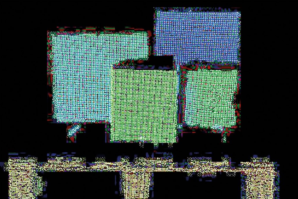
An integrated light source sends out light pulses that strike an object and are reflected back to the camera. The distance and thus the depth value of each individual pixel is calculated on the basis of the time traveled by the light until it reaches the sensor again. This is used to generate a point cloud simply and in real time, while also providing an intensity and confidence map at the same time.
The ToF process is well suited for volume measurements, palletting tasks and autonomous driving vehicles in a logistics and production environment. ToF cameras can also help in the medical field with the positioning and monitoring of patients and in factory automation with robot control and bin picking tasks.

Time-of-Flight cameras in a smart forklift for storage automation
Which technology is suitable for my application?
Just as with 2D cameras, no 3D camera features one single technology that can resolve all tasks. The various requirements must be weighed and prioritized to determine the optimal choice. The following questions are crucial in deciding between technologies for any given application: Do I want to detect the position, shape, presence or orientation of objects? How much precision is wanted and desired? What is the surface condition of the object? What is the working distance and running speed of my application? The desired cost and complexity levels of the planned solution must also match the capabilities of the 3D technology.

Time-of-Flight example