This blog post was originally published at NVIDIA’s website. It is reprinted here with the permission of NVIDIA.
The camera module is the most integral part of an AI-based embedded system. With so many camera module choices on the market, the selection process may seem overwhelming. This post breaks down the process to help make the right selection for an embedded application, including the NVIDIA Jetson.
Camera selection considerations
Camera module selection involves consideration of three key aspects: sensor, interface (connector), and optics.
Sensor
The two main types of electronic image sensors are the charge-coupled device (CCD) and the active-pixel sensor (CMOS). For a CCD sensor, pixel values can only be read on a per-row basis. Each row of pixels is shifted, one by one, into a readout register. For a CMOS sensor, each pixel can be read individually and in parallel.
CMOS is less expensive and consumes less energy without sacrificing image quality, in most cases. It can also achieve higher frame rates due to the parallel readout of pixel values. However, there are some specific scenarios in which CCD sensors still prevail—for example, when long exposure is necessary and very low-noise images are required, such as in astronomy.
Electronic shutter
There are two options for the electronic shutter: global or rolling. A global shutter exposes each pixel to incoming light at the same time. A rolling shutter exposes the pixel rows in a certain order (top to bottom, for example) and can cause distortion (Figure 1).
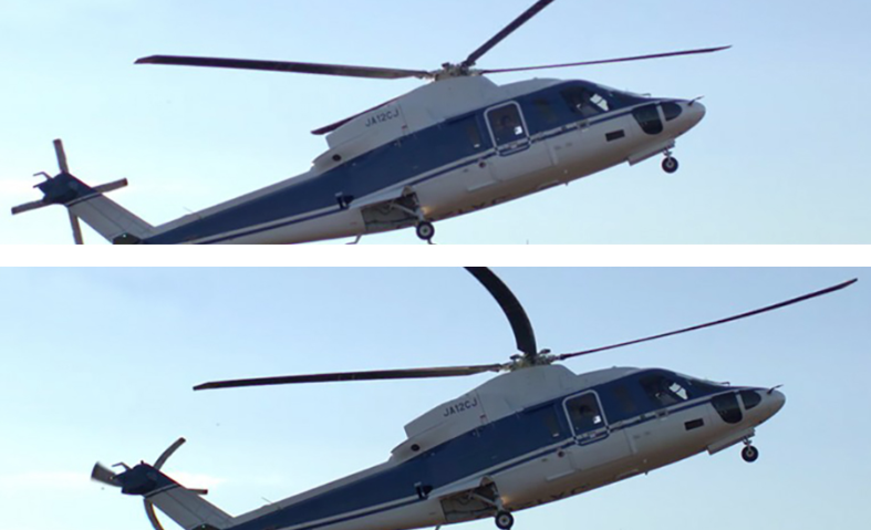
Figure 1. Distortion of rotor blades caused by rolling shutter
The global shutter is not impacted by motion blur and distortion due to object movement. It is much easier to sync multiple cameras with a global shutter because there is a single point in time when exposure starts. However, sensors with a global shutter are much more expensive than those with a rolling shutter.
Color or monochrome
In most cases, a monochrome image sensor is sufficient for typical machine vision tasks like fault detection, presence monitoring, and recording measurements.
With a monochrome sensor, each pixel is usually described by eight bits. With a color sensor, each pixel has eight bits for the red channel, eight bits for the green channel, and eight bits for the blue channel. The color sensor requires processing three times the amount of data, resulting in a higher processing time and, consequently, a slower frame rate.
Dynamic range
Dynamic range is the ratio between the maximum and minimum signal that is acquired by the sensor. At the upper limit, pixels appear white for higher values of intensity (saturation), while pixels appear black at the lower limit and below. An HDR of at least 80db is needed for indoor application and up to 140db is needed for outdoor application.
Resolution
Resolution is a sensor’s ability to reproduce object details. It can be influenced by factors such as the type of lighting used, the sensor pixel size, and the capabilities of the optics. The smaller the object detail, the higher the required resolution.
Pixel resolution translates to how many millimeters each pixel is equal to on the image. The higher the resolution, the sharper your image will be. The camera or sensor’s resolution should enable coverage of a feature’s area of at least two pixels.
CMOS sensors with high resolutions tend to have low frame rates. While a sensor may achieve the resolution you need, it will not capture the quality images you need without achieving enough frames per second. It is important to evaluate the speed of the sensor.
A general rule of thumb to determine the resolution needed for the use case is shown below and in Figure 2. The multiplier (2) represents the typical desire to have a minimum two pixels on an object in order to successfully detect it.

INSERT GRAPHIC
Figure 2. Sensor resolution required is determined by lens field of view and feature of interest size
For example, suppose you have an image of an injury around the eye of a boxer.
- FOV, mm = 2000mm
- Size of feature of interest (the eye), mm = 4mm

Based on the calculation, 1000 x 1000, a one-megapixel camera should be sufficient to detect the eye using a CV or AI algorithm.
Note that a sensor is made up of multiple rows of pixels. These pixels are also called photosites. The number of photons collected by a pixel is directly proportional to the size of the pixel. Selecting a larger pixel may seem tempting but may not be the optimal choice in all the cases.
| Small pixel | Sensitive to noise (-) | Higher spatial resolution for same sensor size (+) |
| Large pixel | Less sensitive to noise (+) | Less spatial resolution for same sensor size (-) |
Table 1. Pros and cons of small and large pixel size
Back-illuminated sensors maximize the amount of light being captured and converted by each photodiode. In front-illuminated sensors, metal wiring above the photodiodes blocks off some photons, hence reducing the amount of light captured.
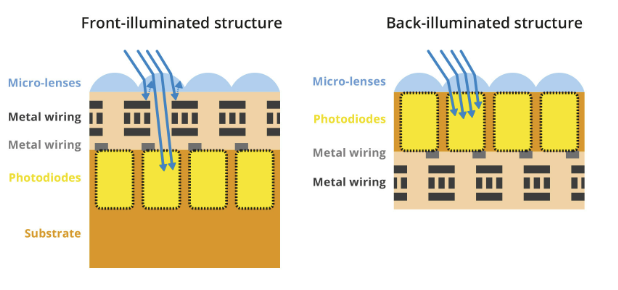
Figure 3. Cross-section of a front-illuminated structure (left) and a back-illuminated structure (right)
Frame rate and shutter speed
The frame rate refers to the number of frames (or images captured) per second (FPS). The frame rate should be determined based on the number of inspections required per second. This correlates with the shutter speed (or exposure time), which is the time that the camera sensor is exposed to capture the image.
Theoretically, the maximum frame rate is equal to the inverse of the exposure time. But achievable FPS is lower because of latency introduced by frame readout, sensor resolution, and the data transfer rate of the interface including cabling.
FPS can be increased by reducing the need for large exposure times by adding additional lighting, binning the pixels.
CMOS sensors can achieve higher FPS, as the process of reading out each pixel can be done more quickly than with the charge transfer in a CCD sensor’s shift register.
Interface
There are multiple ways to connect the camera module to an embedded system. Typically, for evaluation purposes, cameras with USB and Ethernet interfaces are used because custom driver development is not needed.
Other important parameters for interface selection are transmission length, data rate, and operating conditions. Table 2 lists the most popular interfaces. Each option has its pros and cons.
| Features | USB 3.2 | Ethernet (1 GbE) | MIPI CSI-2 | GMSL2 | FPDLINK III |
| Bandwidth | 10Gbps | 1Gbps | DPHY 2.5 Gbps/lane CPHY 5.71 Gbps/lane | 6Gbps | 4.2Gbps |
| Cable length supported | < 5m | Up to 100m | <30cm | <15m | <15m |
| Plug-and-play | Supported | Supported | Not supported | Not supported | Not supported |
| Development costs | Low | Low | Medium to high | Medium to high | Medium to high |
| Operating environment | Indoor | Indoor | Indoor | Indoor and outdoor | Indoor and outdoor |
Table 2. Comparison of various camera interfaces
Optics
The basic purpose of an optical lens is to collect the light scattered by an object and recreate an image of the object on a light-sensitive image sensor (CCD or CMOS). The following factors should be considered when selecting an optimized lens-focal length, sensor format, field of view, aperture, chief ray angle, resolving power, and distortion.
Lenses are manufactured with a limited number of standard focal lengths. Common lens focal lengths include 6mm, 8mm, 12.5mm, 25mm, and 50mm.
Once you choose a lens with a focal length closest to the focal length required by your imaging system, you need to adjust the working distance to get the object under inspection in focus. Lenses with short focal lengths (less than 12mm) produce images with a significant amount of distortion.
If your application is sensitive to image distortion, try to increase the working distance and use a lens with a higher focal length. If you cannot change the working distance, you are somewhat limited in choosing an optimized lens.
| Wide-angle lens | Normal lens | Telephoto lens | |
| Focal length | <=35mm | 50mm | >=70mm |
| Use case | Nearby scenes | Same as human eye | Far-away scenes |
Table 3. Main types of camera lenses
To attach a lens to a camera requires some type of mounting system. Both mechanical stability (a loose lens will deliver an out-of-focus image) and the distance to the sensor must be defined.
To ensure compatibility between different lenses and cameras, the following standard lens mounts are defined.
| Most popular | For industrial applications | |
| Lens mount | M12/S mount | C-mount |
| Flange focal length | Non-standard | 17.526mm |
| Threads (per mm) | 0.5 | 0.75 |
| Sensor size accommodated (inches) | Up to ⅔ | Up to 1 |
Table 4. Common lens mounts used in embedded space
NVIDIA camera module partners
NVIDIA maintains a rich ecosystem of partnerships with highly competent camera module makers all over the world. See Jetson Partner Supported Cameras for details. These partners can help you design imaging systems for your application from concept to production for the NVIDIA Jetson.
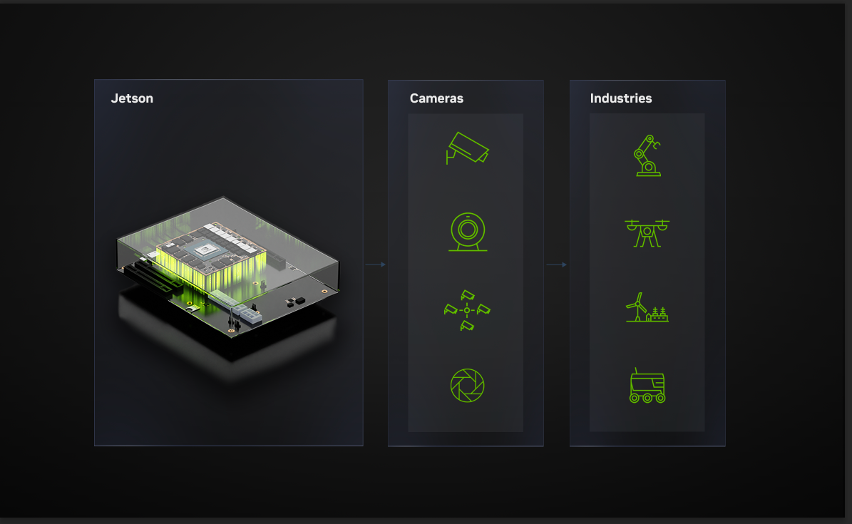
Figure 4. NVIDIA Jetson in combination with camera modules can be used across industries for various needs
Summary
This post has explained the most important camera characteristics to consider when selecting a camera for an embedded application. Although the selection process may seem daunting, the first step is to understand your key constraints based on design, performance, environment, and cost.
Once you understand the constraints, then focus on the characteristics most relevant to your use case. For example, if the camera will be deployed away from the compute or in a rugged environment, consider using the GMSL interface. If the camera will be used in low-light conditions, consider a camera module with larger pixel and sensor sizes. If the camera will be used in a motion application, consider using a camera with a global shutter.
To learn more, watch Optimize Your Edge Application: Unveiling the Right Combination of Jetson Processors and Cameras. For detailed specs on AI performance, GPU, CPU, and more for both Xavier and Orin-based Jetson modules, visit Jetson Modules.
Related resources
- GTC session: Real-Time Onboard Processing for Autonomous Indoor Drones using NVIDIA Jetson (Spring 2023)
- GTC session: Jetson Edge AI Developer Days: Getting the Most Out of Your Jetson Orin Using NVIDIA Nsight Developer Tools (Spring 2023)
- SDK: JetPack SDK
- Webinar: Implementing Computer Vision and Image Processing Solutions with VPI
- Webinar: ACCELERATE COMPUTER VISION AND IMAGE PROCESSING USING VPI 1.1
- Webinar: JetPack 5.0 Deep Dive: New Kernel, Bootloader, Trusted OS and Support for Jetson AGX Orin
Vikas Sharma
Product Manager, NVIDIA