Augmented reality (AR) and related technologies and products are becoming increasingly popular and prevalent, led by their adoption in smartphones, tablets and other mobile computing and communications devices. While developers of more deeply embedded platforms are also motivated to incorporate AR capabilities in their products, the comparative scarcity of processing, memory, storage, and networking resources is challenging, as are cost, form factor, power consumption and other constraints. Fortunately, however, by making effective use of all available compute capabilities in the design, along with leveraging APIs, middleware and other software toolsets, these challenges are largely and increasingly surmountable.
Augmented reality (AR) and related technologies such as Microsoft’s HoloLens and other “mixed reality” platforms are, along with virtual reality (VR), one of the hottest topics in technology today. Applications such as Pokémon Go have generated widespread awareness of AR in the general public, both Apple and Google have recently launched software development kits (ARKit and ARCore, respectively) to further cultivate developer activity in this area, and available middleware toolsets also promise to enable broad multi-platform support while simultaneously maximizing application efficiency on each target platform.
However, many of the existing implementations are based on smartphones and tablet computers, which are the primary topic focus of a previously published article in this series. While these platforms have cost, power consumption, and form factor challenges, they typically also offer an abundance of heterogeneous compute resources (multi-core CPUs, GPUs, DSPs, dedicated-function coprocessors, etc.), memory resources, and robust network connectivity. What about platforms that aren’t resource-blessed: head-mounted displays (HMDs), smart glasses, automotive heads-up displays (HUDs), and the like?
This article discusses implementation options for delivering robust AR functionality in such deeply embedded designs, which are characterized by a scarcity of compute, memory and connectivity resources, along with having cost, power consumption (and heat dissipation), size and weight, and other constraints. It provides general concept recommendations for both hardware and software development, along with specific detailed explanations in the form of case study examples. And it also introduces readers to an industry alliance created to help product creators incorporate vision-enabled AR capabilities into their SoCs, systems and software applications, along with outlining the technical resources that this alliance provides (see sidebar “Additional Developer Assistance“).
Platform and Algorithm Alternatives
AR, VR and mixed (AR-plus-VR) system designs have varying capabilities, translating into varying amounts and types of both processing resources and the software functions that run on them. The following section, authored by Synopsys, explores these topics.
AR and VR differ in fundamental ways. Using images and sounds, VR seeks to create an immersive environment for a headset user, one entirely different than the environment the user is actually in (Figure 1). A VR headset could play back a multimedia recording that the user had previously made of a café in Budapest, for example, or could use virtualized images and sound to insert the user into a video game. Such simulated environments require heavy-duty audio, graphics and video processing “engines” in order to construct the virtual worlds.
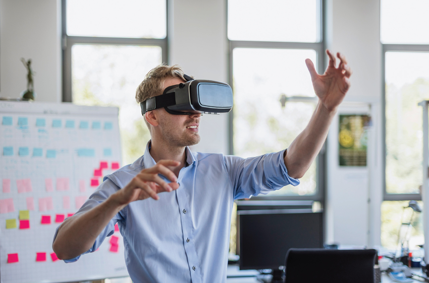
Figure 1. VR HMDs create a fully immersive and alternative environment experience (courtesy Synopsys).
AR, on the other hand, as its name implies merges simulated images, graphics and audio with those of the real world. A user could walk past that previously mentioned café in Budapest wearing AR goggles, for example, and see a graphical list of the daily specials overlaid on the café’s front window. AR is only partially simulated. The real-world aspect of AR requires computer vision in order to discern and identify the surroundings, so that AR can add the virtual world to them.
Mixed reality falls in-between AR and VR and doesn’t have a singular definition; instead it encompasses a range of implementations. While it might still be fully simulated, for example, it might also have the ability to classify and include real-world elements with accurate positions in the virtual world—recognizing your hands so your cartoon self can hold a wand in a wizard game, for example, or recognizing your furniture and replacing it with cartoon furniture or furniture-sized rocks from an alien landscape. Like AR, mixed reality requires the use of various computer vision techniques to detect, identify and locate real-world elements.
SLAM for Localization and Mapping
In order for hardware devices to see the real world around them and augment that reality with inserted images and/or graphics, they need to be able to both determine their position in 3D space and map the surrounding environment. In a controlled setting, markers—2D symbols such as QR codes—enable a camera to determine its position and orientation relative to a surface. However, applications such as automotive, where you can’t insert markers along every stretch of road, must work robustly in a marker-less uncontrolled environment.
In situations like these, simultaneous localization and mapping (SLAM) algorithms, which originated in robotics research, can alternatively provide geometric position for the AR system. SLAM is capable of building 3D maps of an environment, along with tracking the location and position of the camera in that environment. These algorithms estimate the position of the image sensor while simultaneously modeling the environment to create a map (Figure 2). Knowledge of the sensor’s position and pose, in combination with the generated 3D map of the environment, enables the device (therefore the user of the device) to accurately navigate the environment.
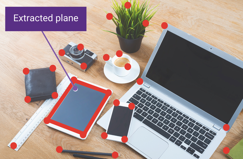
Figure 2. SLAM algorithms, used in marker-less i.e. uncontrolled environments, build a 3D map of the surroundings by identifying points and edges of objects and performing plane extraction from the data (courtesy Synopsys).
SLAM can be implemented in a variety of ways. Visual SLAM, for example, is a camera-centric approach that doesn’t require the inclusion of inertial measurement units (IMUs) or expensive laser sensors in the design. Monocular visual SLAM, an increasingly popular approach, relies on a single camera, as its name implies.
A typical implementation of monocular visual SLAM encompasses several key tasks:
- Feature extraction or the identification of distinct landmarks (such as the lines forming the edge of a table). Feature extraction is often done with algorithms such Features from Accelerated Segment Test (FAST), Binary Robust Independent Elementary Features (BRIEF), Oriented FAST and rotated BRIEF (ORB), Scale-invariant Feature Transform (SIFT), and Speeded-up Robust Features (SURF).
- Feature matching between frames to determine how the motion of the camera has changed.
- Camera motion estimation, including loop detection and loop closure (addressing the challenge of recognizing a previously visited location).
All of these tasks are compute-intensive and will have a significant influence on the hardware chosen for an AR system.
Deep Learning for Perception
While SLAM provides the ability to determine a camera’s location in the environment, along with a 3D model of that environment, accurately recognizing objects in the environment requires a different technique. Deep learning algorithms such as convolutional neural networks (CNNs) are the increasingly prevalent approach to solving this particular problem.
Assuming that the neural network’s coefficients have previously been comprehensively trained, CNNs can be very accurate when subsequently performing object identification (inference) tasks including localization (identifying the location of a particular object in an image) and classification (identifying the object e.g., dog versus cat, or Labrador Retriever versus German Shepherd). While SLAM can help a camera (and user of that camera) move through an environment without running into objects, CNN can identify that a particular object is a couch, refrigerator, or desk, along with highlighting where it is located in the field of view. Popular CNN graphs for real-time object identification are You Only Look Once (Yolo) v2, Faster Region CNN (R-CNN) and Single Shot MultiBox Detector (SSD).
CNN object detection graphs can be specialized to, for example, detect faces or hands. With CNN-based facial detection and recognition, AR systems are capable of adding a name and other social media-sourced information above a person’s face in the AR environment. Using CNN to detect the user’s hands allow game developers to place an object in the player’s virtual hand. Detecting a hand’s existence is easier than determining the hand positioning. Some CNN-based solutions require a depth camera output as well as RGB sensor output to train and execute a position-aware CNN graph.
CNNs can also be successfully applied to the semantic segmentation challenge. Unlike object detection, which only cares about the particular pixels in an image that might be an object of interest, semantic segmentation is concerned about every pixel. For example, in an automotive scene, a semantic segmentation CNN would label all of the pixels that represent sky, road, buildings, and individual cars as a group, a critical capability for self-driving car navigation Applied to AR, semantic segmentation can identify the ceiling, walls and floor, as well as furniture or other objects in the space. Semantic knowledge of a scene enables realistic interactions between real and virtual objects.
Hardware Implementations
SLAM and CNN algorithms both demand a significant amount of computation processing per camera-captured image (frame). Creating a seamless environment for the AR user—merging the real world and virtual world without significant latency – requires a video frame rate of 20-30 frames per second (fps). This requirements means that the AR system has 33-40ms to capture, process, render and display each frame’s results to the user. The faster the system it can complete these tasks, the faster the frame rate and the more realistic the resultant AR seems.
When developing a SoC for a monocular SLAM system, for example, computational efficiency and memory optimization are both critical design parameters. If the camera captures 4K resolution images at 30 fps, these specifications translate into the need to store and process 8,294,400 pixels per frame, and 248,832,000 pixels per second. Commonly, embedded vision systems store each frame in an external DDR SDRAM buffer and then, as efficiently as possible, sequentially transfer portions of the frame for subsequent processing (Figure 3).
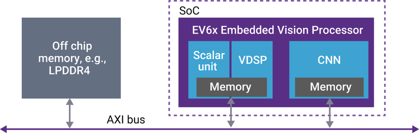
Figure 3. Vision data is stored in off-chip memory and transferred to the processor over the AXI bus (courtesy Synopsys).
Running the algorithms necessary for advanced AR systems solely on a CPU is likely an inefficient approach to solving the problem. Alternatively offloading portions of the algorithms to a GPU, which is likely already present in an AR system for rendering graphics, will notably speed up SLAM and CNN calculations compared to the CPU-only approach. However, relying on the GPU for both graphics and AR processing may sub-optimize the performance of both operations, and can also come at a significant power consumption penalty.
An alternative SoC architectural approach, which trades off incremental core-count complexity for per-core operational efficiency, involves allocating embedded vision algorithm processing to dedicated-function cores. Performance and power consumption optimization can be achieved, for example, by pairing a flexible CNN engine with a vector DSP. The vector DSP is designed to handle algorithms like SLAM, while the dedicated CNN engine supports common deep learning functions (convolutions, pooling, element-wise operations, etc.) and delivers silicon area and power consumption efficiency because it is custom-designed for these parameters.
Synopsys’ EV6x Embedded Vision Processor IP is one leading option for providing an optimized solution to address performance, power consumption and other SoC design concerns. The DesignWare EV61, EV62 and EV64 Embedded Vision Processors integrate a high-performance 32-bit scalar core with a 512-bit vector DSP, along with a optional CNN engine for accurate object detection, classification, and scene segmentation.
The vector DSPs are ideal for executing the SLAM algorithm and run independently of the CNN engine. The EV6x family delivers up to 4.5 TeraMACs/sec of CNN performance when implemented in 16-nm processes under typical conditions, and supports multiple camera inputs each with up-to-4K resolution. The processors are fully programmable and configurable, combining the flexibility of software solutions with the high performance and low power consumption of dedicated hardware.
Gordon Cooper
Product Marketing Manager, Synopsys
Software Optimizations
Creating an efficient implementation of an AR application for a single target hardware platform is challenging enough for a software developer; successfully doing so across a range of platforms is even more difficult. The following section, authored by PTC, offers suggestions for actualizing this aspiration, including proposing a middleware option.
The computational complexities to be solved in order to facilitate robust AR are significant and increasingly diverse, considering that the tasks involved include image processing for 3D reconstruction, high-speed motion estimation and prediction, and a variety of 2D and 3D object recognition algorithms, along with networking support for various cloud-based functions. This interplay between hardware and software becomes even more critical when you consider that AR applications often require additional processing resources, such as for intricate 3D renderings and elaborate user interfaces to create compelling and effective AR experiences. PTC’s Vuforia Chalk application, for example, significantly burdens the camera-video codec pipeline and network stack in facilitating a rich collaborative AR experience between a local technician and a remote expert (Figure 4).
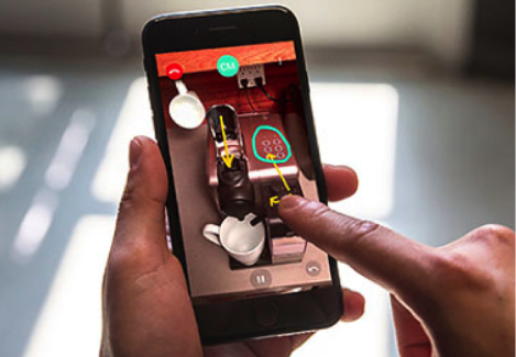
Figure 4. Vuforia Chalk supports marker-less tracking and annotation (courtesy PTC).
For AR app developers, device diversity is a high hurdle to surmount. Every model of SoC (sometimes even extending to individual devices within a given model) exhibits specific idiosyncrasies related to differing hardware configurations. And today’s operating systems and libraries don’t sufficiently “hide” this differentiation for the precision and accuracy that AR demands, even within a particular vendor’s SoC offerings. A cross-platform AR application development kit, such as the Vuforia Engine, provides reliable performance and a consistent user experience, largely due to its extensive, underlying platform-specific implementations and calibrations.
As a leading AR middleware toolset for application developers, the Vuforia Engine has long provided a rich and technically advanced software abstraction layer for AR functionality, including target detection, marker-less tracking, and ground plane detection. The Vuforia Engine abstracts hardware and operating system software (Apple’s iOS, Google’s Android, Microsoft’s Universal Windows Platform (UWP) and HoloLens, and products from ODG and Vuzix, to name just a few) but makes use of underlying hardware and software capabilities whenever possible, such as IMUs, GPUs, and the ARKit and ARCore APIs.
Optimizations aside, the Vuforia Engine still needs to be extremely resource-conscious. As such, PTC collaborates with numerous partners to improve the aforementioned hardware-and-software interplay. Manufacturers of AR products, along with the sensors and ICs contained within them, will in the future see ever-increasing demand to implement optimized hardware capabilities as well as expose core sensor characteristics and measurements in order to facilitate ever-more-optimized middleware. These improvements encompass the camera and its calibration aspects, especially as optical image stabilization and multi-lens kits become increasingly commonplace.
To date, more than 60,000 commercial AR applications have been enabled by the Vuforia Engine, resulting in more than 600 million installs. PTC continually works closely with its community of more than 500,000 developers, along with shipping its own Vuforia platform applications for the industrial enterprise market. The following recommendations, derived from these experiences, will be useful to application developers:
- Continually profile the application on all supported devices, including static and memory footprint analyses. Build it with profiling in mind, both for troubleshooting in the test lab and for for real-time feedback in the end application. Application tuning in response to O/S notifications on device state (memory usage, operating temperature, network load, etc.) is critical for a satisfying user experience.
- AR capabilities are particularly valued by users in mobile and field applications. Expect widely and rapidly varying network coverage; the application should be bandwidth-conscious and adapt quickly as connectivity conditions change over time.
- Utilize optimized platform software when available, but closely evaluate fit and performance before committing. For example, cutting-edge O/S capabilities might not provide the necessary quality in their initial versions.
- Hardware sensor particularities have a significant impact on tracking accuracy. Consider careful calibration with respect to temporal and spatial aspects for every hardware sensor model, not just for the integrated device model.
- Given the diversity in hardware capabilities among platforms, such as between smartphones and digital eyewear, tailored approaches to providing AR capabilities should be employed in various cases. For example, extensive processing is required on a typical smartphone for 3D reconstruction, whereas the Microsoft HoloLens depth sensors and API deliver these capabilities for “free.”
- Don’t underestimate the importance of the user interface. An AR experience combines the physical world, a digital experience and the movement of a human being in order to map content to the environment. Guiding the human simply, yet successfully, is crucial to application success.
- AR delivers most value if the experience references real objects in the environment and offers interaction with them. Vuforia’s Model Targets, for example, precisely register a 3D model on industrial machinery, tying the digital and physical worlds together and enabling interaction both ways, via IoT sensors embedded in the machinery and contextual, virtual information displayed accurately on physical components (Figure 5).
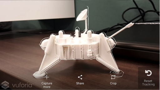
Figure 5. Vuforia’s Model Targets implement object detection and tracking based on a 3D CAD model (courtesy PTC).
Mathias Kölsch
Senior Director for Software Engineering, Vuforia, a PTC Technology
Implementation Case Study: A Head-mounted Display
As the introductory section of this article notes, HMDs such as the Meta 2 or products from DAQRI are one key target platform for resource-intensive AR, but (like other embedded systems covered by this article) HMDs are comparatively resource-constrained versus, say, a smartphone or tablet computer. The following section, authored by videantis, details a conceptual design that’s applicable to both AR and “mixed reality” products.
A high-end HMD architecture, focusing here on the imaging and video paths (therefore excluding the IMU, audio, and haptics systems) includes numerous cameras (Figure 6). Image sensors are used, for example, for gaze tracking in order to discern where the user’s eyes are looking. This feature enables, for example, gaze contingency, wherein an AR screen display dynamically alters its regional graphical resolution and other rendering characteristics depending on where within it the viewer is looking. Another use for gaze tracking is to employ the eyes as a cursor pointer. Multiple cameras are also included for head tracking purposes, since the inclusion of outward-looking and camera-based trackers can deliver much more accurate results versus only using IMUs.
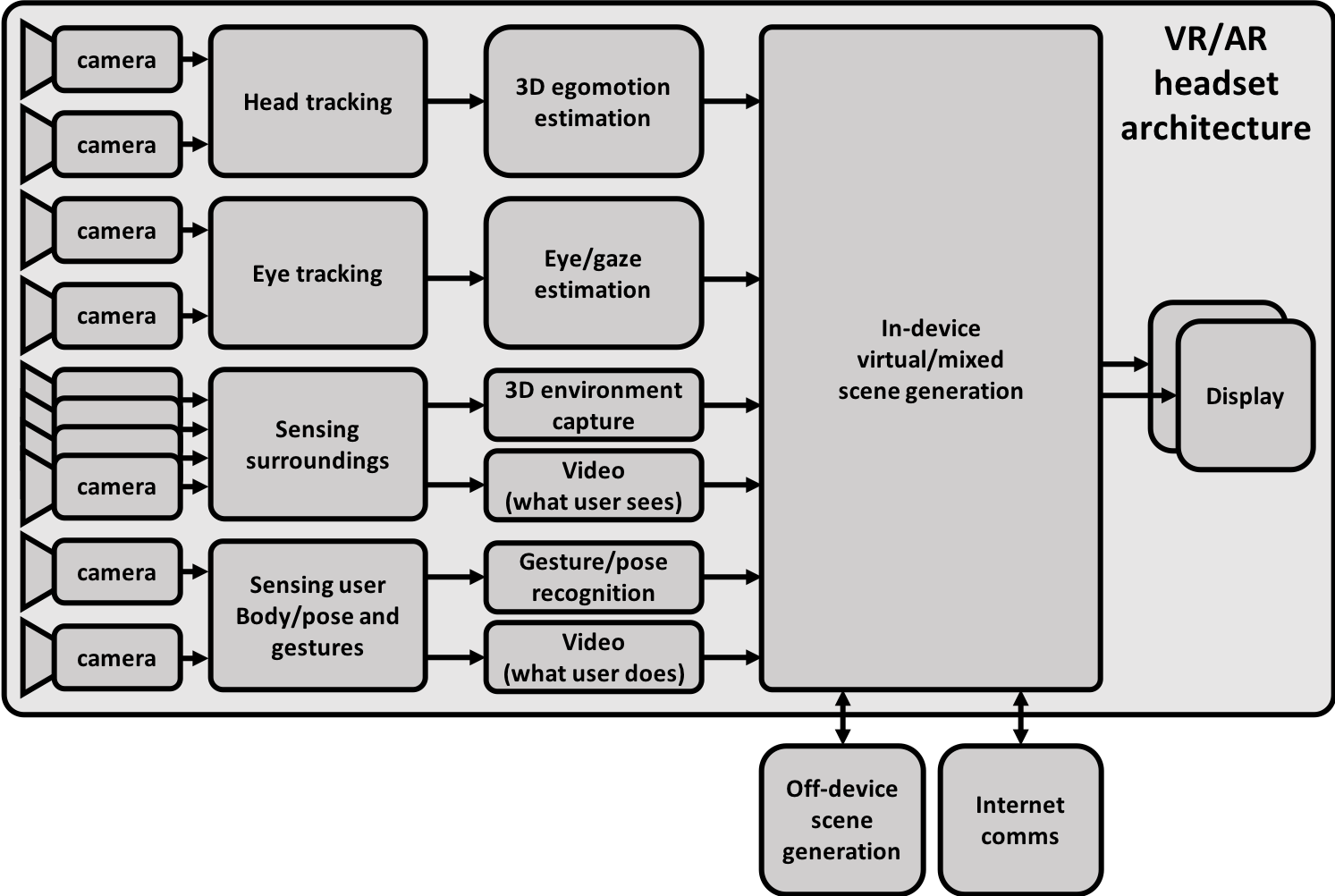
Figure 6. A high-end HMD architecture block diagram includes multiple image sensors for a variety of purposes (courtesy videantis).
Additional outward-looking cameras are included to sense the user’s surroundings. Ideally, they will capture a full 3D and real-time reconstruction of the environment around them. This way, virtual objects can then be correctly aligned to and “locked into place” within the real environment. Capture of a video stream of what the user sees can potentially occur in order to present a view of the surroundings onto the displays in front of the user’s eyes (a pair of cameras may be needed to present a correct stereo view for the two eyes) and for forwarding to other (remote) users. And even more cameras can be included to capture the user’s body position and gestures (again, a video stream of the same could also be captured for forwarding to remote users).
Different HMD implementations may use fewer (or potentially even more) cameras than what’s shown here. VR headsets, a functional subset of the architecture shown, typically require only head, eye, and body/gesture tracking capabilities, for example. And although in an ideal system, you’d include a separate camera for each individual sensing and capturing task, a single camera can alternatively handle multiple functions, thereby reducing the total number of cameras in the system, lowering cost and power consumption, and making the headset smaller and lighter.
Keep in mind when attempting to use a single camera for multiple functions, however, that the tasks that the camera(s) are being used for fundamentally define their requirements. For example, the ideal location and position of each camera for each function in the headset may vary. Resolutions, frame rates, rolling versus global shutter mechanisms, monochrome versus color filters, and other attributes may also be dissimilar for different visual functions. A camera intended for sensing the user’s gestures, for example, is typically based on a monochrome depth sensor optimized for short distances, while a camera for head tracking needs higher resolution, a higher frame rate, and the ability to capture more distant scenes.
Keep in mind, too, that “behind” each camera is an embedded vision processing chain; the cumulative power consumption of all of these computational modules, along with associated memory and other components, can reach high levels quickly, not to mention the added power consumption of the cameras themselves. And even more power consumption (and related heat dissipation) comes from the significant graphics processing resources in the rendering path that generates high-quality, high-resolution 3D scenes in front of each eye. Finding off-the-shelf components that can provide the many required camera interfaces and associated compute resources and still fit in a reasonably small and lightweight headset is often challenging.
This reality has resulted in some HMD designers deciding to subdivide the total system into two portions: the headset itself, and a (wired, for now, potentially wireless in the future) connected computing module worn on the waist, with the latter allowing for a larger size and weight than what a user could wear (and bear) on the head (analogously, a non-portable AR system may employ a PC as the computing module). In such cases, the vision processing and rendering happens inside the computing module, thereby presenting a different sort of challenge. The multiple cameras’ outputs need to be transmitted from the HMD to the computing module, and the resulting dual display streams from the computing module back to the HMD, over the tether between them. The data will likely need to be compressed prior to transmission, and decompressed after reception, in both directions and with ultra-low latency.
The videantis v-MP6000UDX visual computing architecture is a leading example of a processor that can fulfill multiple roles within an advanced AR, VR or “mixed reality” system. First, as previously mentioned, there’s the wealth of computer vision and deep learning processing tasks that take place “behind” each camera. Secondly, there’s the ultra-low-latency, high-resolution video compression and decompression tasks that are needed in a subdivided configuration with separate HMD and computing module. And lastly, there’s the display rendering path, which requires a programmable imaging pipeline since the eye-tracking-based display systems and their associated display algorithms are still rapidly evolving. Running all of these algorithms on a unified architecture, such as the one which the v-MP6000UDX provides, is beneficial in numerous regards when compared against the alternative of different dedicated processing architectures for each task, an approach which would result in higher system complexity and extra data movement between the different processing systems.
Marco Jacobs
Vice President of Marketing, videantis
Implementation Case Study: An AR-based Automotive Heads-up Display
While you might not automatically think of an automobile when you hear the term “embedded system”, developing automotive electronics involves dealing with notable design challenges. Cost is always a concern, of course, but size and weight are also critical factors when optimizing for vehicle range. And heat dissipation is equally difficult to deal with, especially as the computing intelligence included in vehicles exponentially grows with time. The following section, authored by NXP Semiconductors, provides a pertinent example, an AR-based heads-up display (HUD).
The fundamental premise (and promise) of AR in automobiles is to reduce the risk of accidents, by visually presenting relevant information in the driver’s field of view while still enabling the driver to keep his or her eyes on the road ahead. HUDs based on various display technologies have been used in cars since the 1990s, and you might think that increasing vehicle autonomy over time might make their continued inclusion unnecessary. In actuality, however, the rapid recent advancements in ADAS and autonomous vehicle technologies are driving the need for more and more natural ways of presenting information to the human driver, both to reassure him or her that the vehicle is autonomously operating in an appropriate manner and to effectively alert when he or she needs to regain manual control.
Many implementation challenges exist for HUDs used in vehicles. A HUD needs to display content visible in full sunlight, for example, “hover” the graphics sufficiently ahead so the driver doesn’t need to change focus while driving in order to discern them, and must also have compact dimensions in order to fit in the dashboard. Additionally, the bill-of-materials cost must be low, the HUD must operate without overheating and without need for active cooling, and it must run problem-free for many years. Latest-generation HUDs are also challenged to support a wide field of view (12 degrees or more) along with delivering full-color, high frame rate and high-resolution images.
Today, two primary HUD technologies exist: windshield projection and optical combiners. Reflecting projected data off the windshield delivers optimum coverage, but the implementation is complex, requiring tight integration with each specific vehicle. The exact windshield curvature must be known, for example, in order to deliver optimum quality results; the projector must also output high light intensity in order for the data to be visible on a sunny day. The alternative optical combiner approach is more straightforward from an integration standpoint, since the projection takes place onto a known simpler screen surface. That surface is usually also darker to provide contrast and reduce the sun’s light intensity, so the projector doesn’t need to be as intense as with the alternative windshield projection approach. But the surface area covered by an optical combiner is often quite small.
Also, until very recently, arguably none of the HUD systems available in vehicles were “true” AR; while they projected information on top of the real life scene ahead, they didn’t attempt to integrate with it. However, with the evolution of ADAS technology, high resolution mapping, and 3D graphics, it’s now possible to project data such as navigation information overlaid with the real visual content of the 3D scene—highlighting the lane to follow, for example, or color coding of a suggested speed—just as if that information were actually part of the real world. Additional information likely to be included in the near future includes data sourced from Vehicle-to-Everything (V2X) infrastructure deployments, such as when a traffic light will change, or variations in traffic flow ahead (including impending stoppages)—in other words, any and all information which can prevent accidents and more generally enable reaching destinations faster and easier.
The integration of rich data into the driver’s field of vision requires a 3D understanding of the scene, which is typically achieved by computing SLAM (discussed earlier in this article) on the images coming from a camera mounted such that it looks ahead of the vehicle. The reconstruction of the scene allows for placement of graphics, such as a navigation path, precisely in 3D space. Such integration of graphics within the “real” environment is a much more intuitive (not to mention less distracting) approach for the driver than classical navigation based on audio-only feedback or “bird’s-eye view” visual instructions.
The display of 3D graphics using AR technologies in vehicles is currently at an early deployment stages, exemplified by the European version of the Mercedes-Benz Class-A series. This system presents data on a dedicated display that also includes an augmented video feed of the view ahead of the vehicle; the data includes navigation directions, for example, along with buildings augmented by street address numbers. This approach, however, means that the driver needs to look at the display instead of the windshield road ahead. A promising alternative approach comes from a company called WayRay, whose holographic display technology and software aspire to deliver true HUD-based AR. WayRay’s approach is capable of present 3D graphics directly in the driver’s field of view and without need for a HMD, as demonstrated in Rinspeed AG’s Oasis concept car (Figure 7).
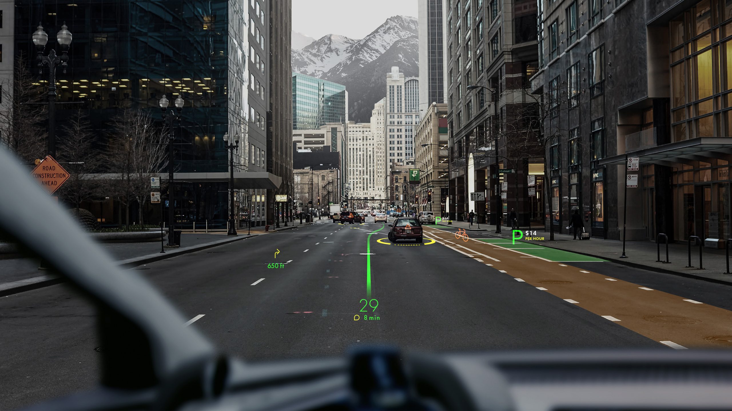
Figure 7. WayRay’s holographic HUD technology delivers rich AR data to the driver (courtesy WayRay).
Stéphane François
Software Program Manager, Vision and AI R&D, NXP Semiconductors
Conclusion
Vision technology is enabling a wide range of products that are more intelligent and responsive than before, and thus more valuable to users. Vision processing can add valuable capabilities to existing products, and can provide significant new markets for hardware, software and semiconductor suppliers. Computer vision-enabled AR is one notable innovation example, although its resource demands have historically been particularly challenging to implement in deeply embedded products. However, by making effective leverage of all available compute capabilities in the design, along with leveraging APIs, middleware and other software toolsets, these challenges are increasingly surmountable.
Brian Dipert
Editor-in-Chief, Embedded Vision Alliance
Senior Analyst, BDTI
Sidebar: Additional Developer Assistance
The Embedded Vision Alliance, a worldwide organization of technology developers and providers, is working to empower product creators to transform the potential of vision processing into reality. NXP Semiconductors, PTC, Synopsys and videantis, the co-authors of this article, are members of the Embedded Vision Alliance. The Embedded Vision Alliance’s mission is to provide product creators with practical education, information and insights to help them incorporate vision capabilities into new and existing products. To execute this mission, the Embedded Vision Alliance maintains a website providing tutorial articles, videos, code downloads and a discussion forum staffed by technology experts. Registered website users can also receive the Embedded Vision Alliance’s twice-monthly email newsletter, Embedded Vision Insights, among other benefits.
The Embedded Vision Alliance’s annual technical conference and trade show, the Embedded Vision Summit, is intended for product creators interested in incorporating visual intelligence into electronic systems and software. The Embedded Vision Summit provides how-to presentations, inspiring keynote talks, demonstrations, and opportunities to interact with technical experts from Embedded Vision Alliance member companies. The Embedded Vision Summit is intended to inspire attendees’ imaginations about the potential applications for practical computer vision technology through exciting presentations and demonstrations, to offer practical know-how for attendees to help them incorporate vision capabilities into their hardware and software products, and to provide opportunities for attendees to meet and talk with leading vision technology companies and learn about their offerings. The next Embedded Vision Summit is scheduled for May 20-23, 2019 in Santa Clara, California. Mark your calendars and plan to attend; more information, including online registration, will be available on the Embedded Vision Alliance website in the coming months.
The Embedded Vision Alliance also offers a free online training facility for vision-based product creators: the Embedded Vision Academy. This area of the Embedded Vision Alliance website provides in-depth technical training and other resources to help product creators integrate visual intelligence into next-generation software and systems. Course material in the Embedded Vision Academy spans a wide range of vision-related subjects, from basic vision algorithms to image pre-processing, image sensor interfaces, and software development techniques and tools such as OpenCL, OpenVX and OpenCV, along with Caffe, TensorFlow and other machine learning frameworks. Access is free to all through a simple registration process. And the Embedded Vision Alliance and its member companies also periodically deliver webinars on a variety of technical topics. Access to on-demand archive webinars, along with information about upcoming live webinars, is available on the Embedded Vision Alliance website.